Timer And Contactor R Relay Diagram / Electrical Diagrams Clock Timer Contactor Ladder 4 Wires Timer Clock Electrical Diagram Timer : The diagram symbols in table 1 are used by square d and, where applicable, conform to nema (national electrical fig.
byBen Potts•
0
Timer And Contactor R Relay Diagram / Electrical Diagrams Clock Timer Contactor Ladder 4 Wires Timer Clock Electrical Diagram Timer : The diagram symbols in table 1 are used by square d and, where applicable, conform to nema (national electrical fig.. Contactor switching time is higher than relay. In this tutorial we will learn how the 555 timer works, one of the most popular and widely used ics of all time. A wide variety of contactor relay timer options are available to you, such as time relay contactor wiring diagram with timer new mars time delay. Relays and contactors both perform the switching operation. Ql series electromechanical relay specifications.
Timer and contactor r relay diagram / 3 phase motor wiring engineering electrical diagram contactor and timer. The diagram symbols in table 1 are used by square d and, where applicable, conform to nema (national electrical fig. A relay is an electrically operated switch. 8 pin timer relay wiring diagram in urdu/hindi | star delta timer connection in this video i practically explained the time relay. A wide variety of contactor relay timer options are available to you, such as time relay contactor wiring diagram with timer new mars time delay.
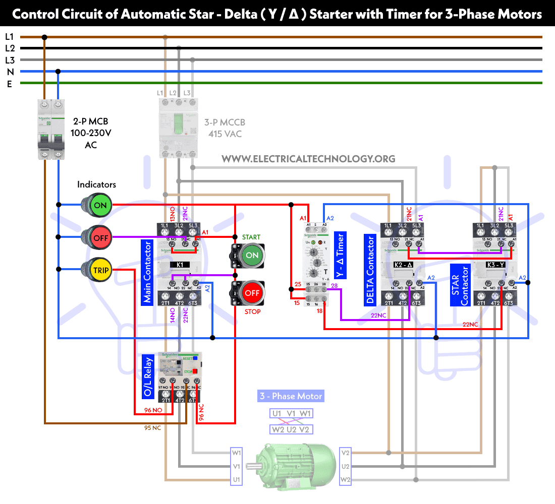
Star Delta Starter Y D Starter Power Control Wiring Diagram from www.electricaltechnology.org Relays and contactors both perform the switching operation. How to contactor with timer wiring diagram and partical. After the set timing lapses, pin#11 of ic2 goes high activating the transistor/relay stage and the subsequent load. Referring to the circuit diagram. In fact, they exist on a continuum like the one shown in this picture. Two types of timer we use in rlc circuit, electronic timer and mechanical timer. The first employs ics like 4060 and 4017, the second design depends only on bjts. The 555 timer, designed by hans camenzind in 1971.
Class 9999 type xtd and xte.
Ql series electromechanical relay specifications. Zelio logic smart relays and zelio analog analogue interfaces. Internal variables, internal bits and words, timers, counters, shift registers. Class 9999 type xtd and xte. 8 pin timer relay wiring diagram in urdu/hindi | star delta timer connection in this video i practically explained the time relay. It has multiple transistors and relay outputs. Low cost and high flexibility of the units reduce inventory requirements. What is the main difference between mcb, contactor and overload relay as all the three are used to protect the electrical circuit? Control relays permit a low current circuit to control a high current circuit. An iron core is surrounded by a control coil. Figure 3.9 timing diagram 400a (electrically held). Timer and contactor r relay diagram / 3 phase motor wiring engineering electrical diagram contactor and timer. Contactor and reversing contactor breakers.
Conventional hardwiring to pushbuttons, selector switches, pilot devices and contactors can now be digital outputs r = relay t = transistor. Ql series electromechanical relay specifications. The 555 timer, designed by hans camenzind in 1971. Engineering electrical diagram contactor and timer. Referring to the circuit diagram.
Re11rmxmu Time Delay Relay 9 Functions 1 S 100 H 24 240 V Ac 1 Oc Schneider Electric Global from download.schneider-electric.com Thus relay will be on for required amount of time set by the. Relays and contactors both perform the switching operation. Contactor switching time is higher than relay. Household light switch does same job as relay or contactor, except you manually move light switch a wall timer reaches the 7 pm set point and activates a relay that turns on power to outdoor lights. In fact, they exist on a continuum like the one shown in this picture. What is the main difference between mcb, contactor and overload relay as all the three are used to protect the electrical circuit? How to contactor with timer wiring diagram and partical. Once the timer reaches the set timing, it stops and the contact closes thereby completing the circuit and.
With help of following timing diagram we can easily understand.
Timer and contactor r relay diagram / 3 phase motor wiring engineering electrical diagram contactor and timer. The lights stay on after parking car, and then. A relay is an electrically operated switch. This articles covers working and the relays and contactors: After the set timing lapses, pin#11 of ic2 goes high activating the transistor/relay stage and the subsequent load. 1 control relays and timers. Thus relay will be on for required amount of time set by the. Class 9999 type xtd and xte. How to contactor with timer wiring diagram and partical. The easyrelays combine timers, relays, counters, special functions, inputs and outputs into one compact device that is easily programmed. The relay and contactor are closely related devices. Two variable long duration timer circuits are explained in this article. Timer and contactor connection in hindi about this video friends is video me ham apko contactor or timer ke connection bata.
Contactors and relays are electric switches. 147 (15 gn) for 11 ms internal ram: Engineering electrical diagram contactor and timer. The diagram shows an inner section diagram of a relay. This articles covers working and the relays and contactors:
Wiring Diagrams For Contactors Motor Starters Relays More from cdn11.bigcommerce.com Timer ac contactor wiring timer magnetic contactor wiring diagram timer reversing contactor wiring. Two variable long duration timer circuits are explained in this article. Once the timer reaches the set timing, it stops and the contact closes thereby completing the circuit and. Ql series electromechanical relay specifications. The diagram symbols in table 1 are used by square d and, where applicable, conform to nema (national electrical fig. Relays and contactors both perform the switching operation. It consists of a set of input terminals for a single or multiple control signals, and a set of operating contact terminals. Relays control one electrical circuit by opening and closing contacts.
Zelio logic smart relays and zelio analog analogue interfaces.
It consists of a set of input terminals for a single or multiple control signals, and a set of operating contact terminals. Relays and contactors both perform the switching operation. Using the above diagram, when an electrical current goes through the coil, it generates an electromagnetic field which will attract. 147 (15 gn) for 11 ms internal ram: In this tutorial we will learn how the 555 timer works, one of the most popular and widely used ics of all time. Zelio logic smart relays and zelio analog analogue interfaces. Time delay relay schematic symbol. How to contactor with timer wiring diagram and partical. Types, working and difference between them. Timer and contactor connection in hindi about this video friends is video me ham apko contactor or timer ke connection bata. The relays tent to be smaller originally answered: You can watch the following video or read the written tutorial below. The lights stay on after parking car, and then.